Design Documentation
Dove Habitat
A modular cage accessory system: 3D-printed mounts and accessories for a wire corner cage
Rev A 20 Oct. 2026
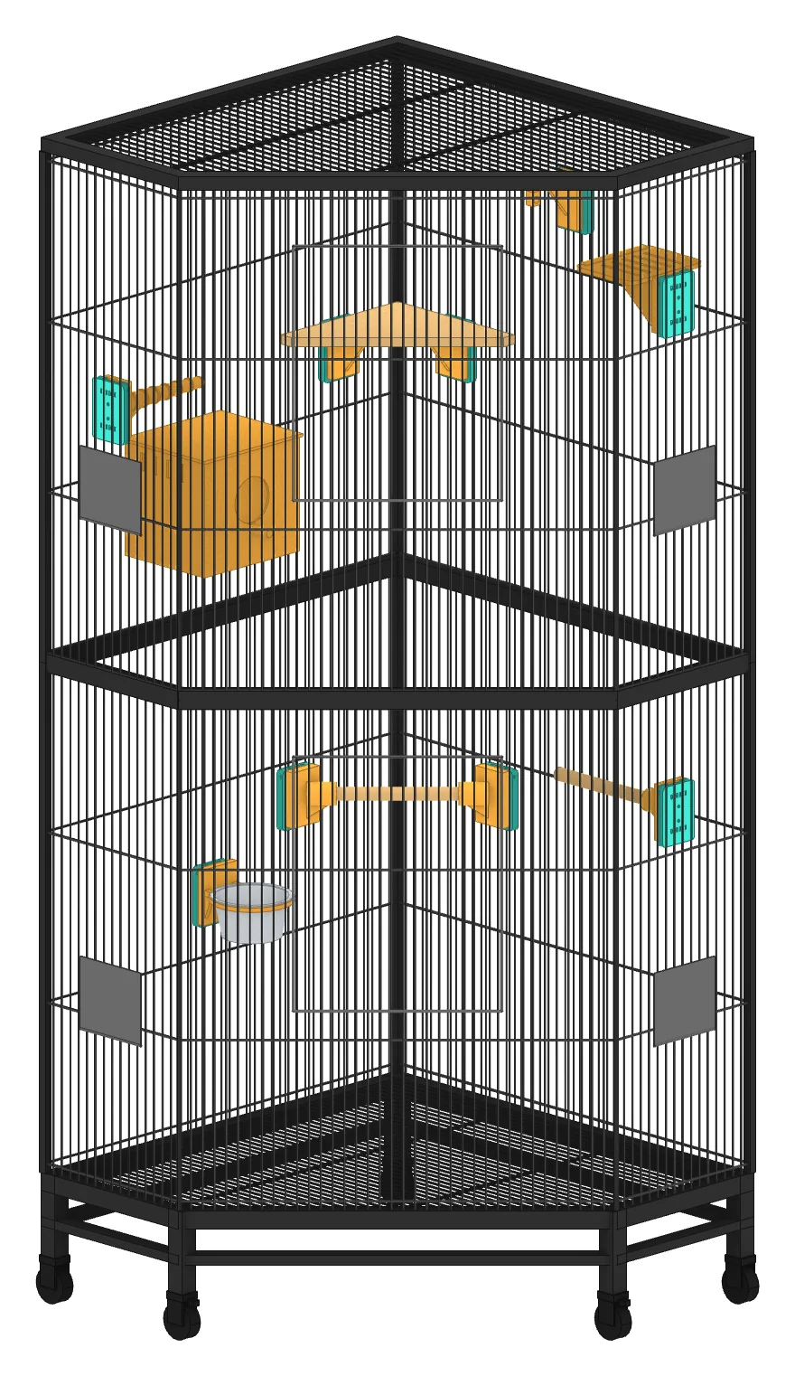
Abstract
Standardised, 3D-printable mounts and accessories for a wire corner cage. Every accessory attaches through the same interface, so any accessory fits on any mount and can be moved or swapped with nothing more than a hex key.
- Accessories
- 9 types
- Interface
- 1, shared by all of them
- Print plates
- 8, no supports
- Wire grid
- 5/8″
Base Cage
Panel Faces
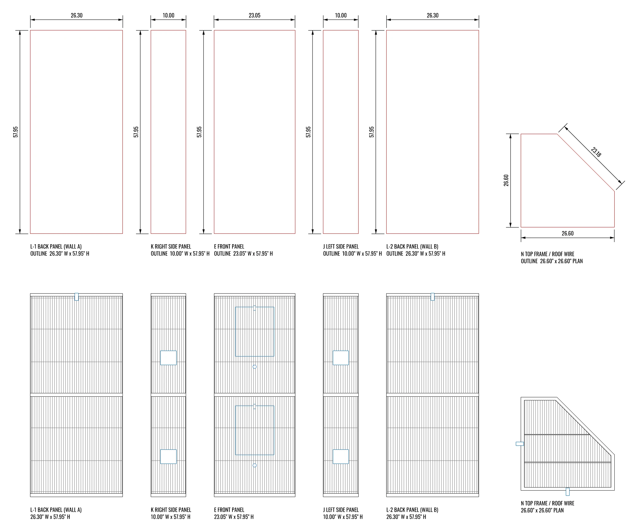
Every panel of the cage laid flat: its measured outline above, its wire, doors and feeder openings below, and the top frame in plan at the right. Inches.
The system is designed around the All Living Things 64″ Tall Corner Home (model 5351668), a two-tier corner cage on casters. Its 5/8″ wire spacing is the grid every mount is designed to.
- Overall
- 26.3″ L × 26.3″ W × 64.1″ H
- Wire spacing
- 5/8″ (15.875 mm)
- Back panels
- L-1, L-2 (walls A, B): 26.30″ W × 57.95″ H
- Side panels
- J (left), K (right): 10.00″ W × 57.95″ H
- Front panel
- E: 23.05″ W × 57.95″ H
- Top frame
- N (roof wire): 26.60″ × 26.60″ plan, 23.18″ diagonal
The Cage As It Comes
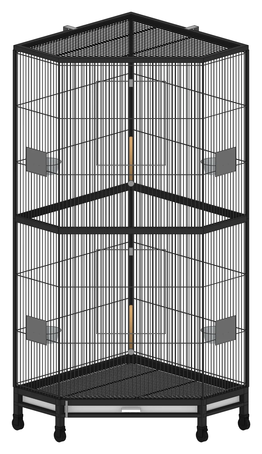
Before any accessory: the cage with its own corner perches, feeder cups and doors.
Standard Interface
The Stack
A PH-1 dowel perch split along its axis, with the cage wire at the left. From the wire outward: the mount, the key adapter, the head and the dowel.
A printed mount clamps to the cage wires once. Accessories then slide into it, lock with a pin, and come out again in seconds. Each accessory is the same stack of layers, from the cage wire outward.
- MP-1 wire mount
- Clamps onto the 5/8″ wire grid. Kit: MP-1, a BP-1 backer and an LK-1 pin, fixed with 4 zip ties or 2 × M4.
- KA-1 key adapter
- A dovetail key that slides down into the mount and is locked by LK-1.
- Swappable head
- Fastens to KA-1 with 4 × M3 screws into heat-set inserts.
- Function parts
- The dowel, cup, deck, board or link that the head carries.
In the split drawings, colour shows what each part does: teal for the mount, blue for the key adapter, orange for structure, green for a perch, red for feeding, purple for a platform, yellow for shelter, pink for a toy, tan for wood to buy or cut, and grey for hardware to buy.
Design Principles
- Built to the grid
- The mount’s four wire grooves sit on the cage’s 15.875 mm pitch; NB-1’s two keys are exactly six wires apart.
- Quick swaps
- Pull the pin, lift the accessory out, drop another in.
- Printable as is
- Every part is laid out in print orientation on a 220 mm bed, with no supports.
MP-1 Back
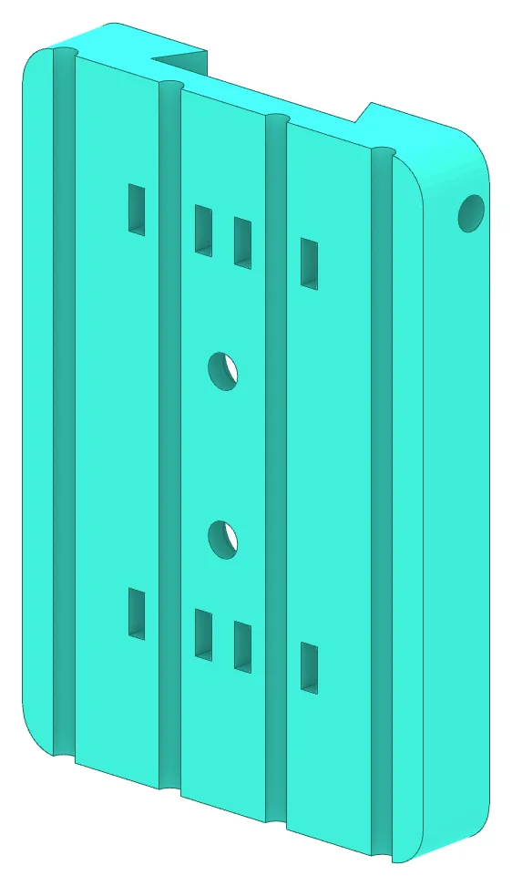
Wire grooves at 5/8″ pitch, zip-tie slots, M4 holes.
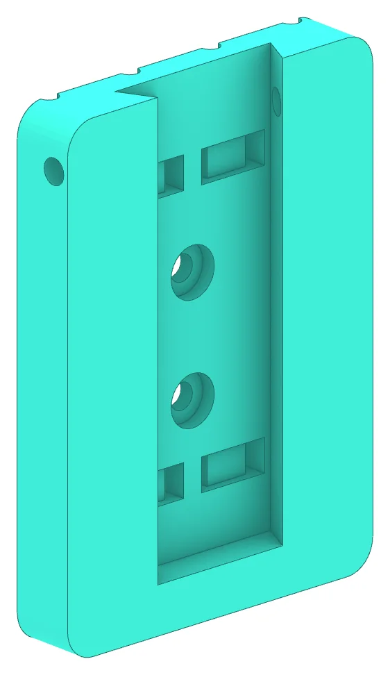
MP-1 Front
Dovetail channel, open top, 6 mm bottom stop, LK-1 bore.
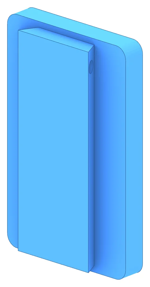
KA-1 Back
Dovetail tongue with the LK-1 cross-bore.
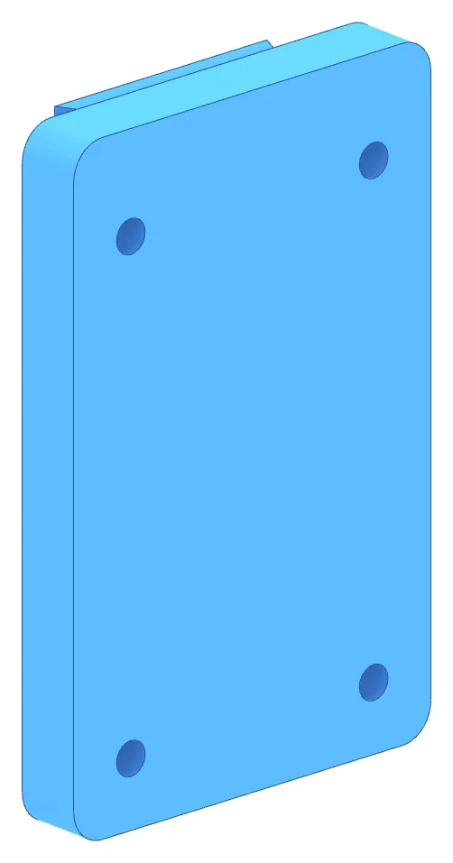
KA-1 Front
4 × Ø4.0 mm insert holes on a 34 × 58 mm pattern.
Section
BP-1, the cage wires, MP-1, KA-1 and a PH-1 head, cut at mid-height. The wires sit at 15.875 mm (5/8″) pitch. Millimetres.
Front Views
Dashed: the dovetail flanks, the LK-1 bore and the wire grooves behind. Millimetres.
Key Dimensions
- Wire pitch
- 15.875 mm (5/8″)
- Dovetail channel
- 25 mouth, 30.4 base, 6 deep
- Dovetail tongue
- 23.6 root, 29.6 tip, 6.2 high
- Head pattern
- 4 × M3 on 34 × 58 mm
- M4 holes (MP-1)
- Ø4.4, Ø8.5 counterbore, 20 apart
- LK-1 bore
- Ø4.3, 8 below top
Wire Side
BP-1, zip ties, MP-1, LK-1.
Accessory Side
Fixing a Mount
| Zip-tie | Bolted | |
|---|---|---|
| Parts | MP-1, LK-1, 4 × 4.8 mm ties | MP-1, LK-1, BP-1, 2 × M4 + nuts |
| Access | Inside only | Both sides |
| Use | Most accessories | Heavy accessories, busy spots |
Centre MP-1 over four vertical wires with the channel opening upward, clear of cross-bars, doors and frames. Lower the key in until it rests on the stop, then push LK-1 through the side bore.
Accessories
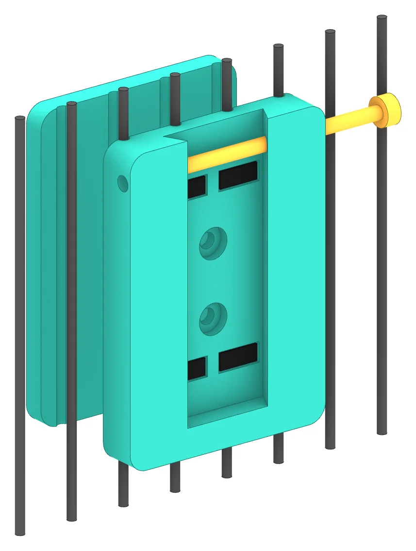
MP-1 Wire Mount Kit
12 mm reach1 mount
The one fixing point on the cage. Every accessory locks into it.
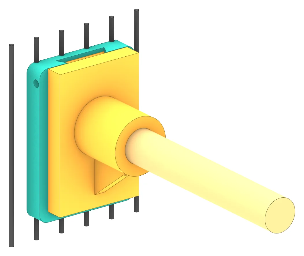
PH-1 Dowel Perch
174 mm reach1 mount
A straight perch from any length of 3/4″ hardwood dowel.
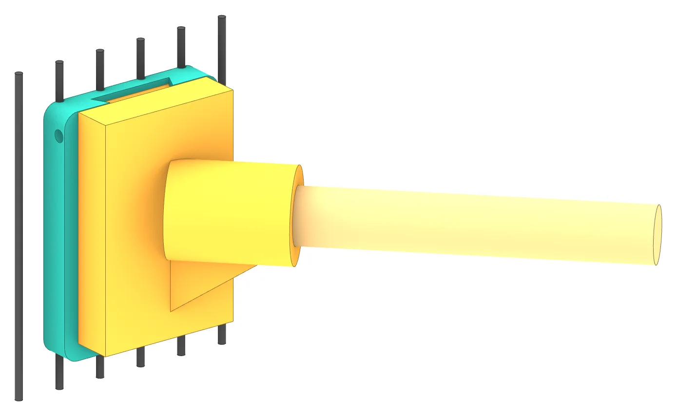
PH-2 Corner Perch
142 mm reach1–2 mounts
PH-1 with the socket turned 45°, in mirrored L and R versions.
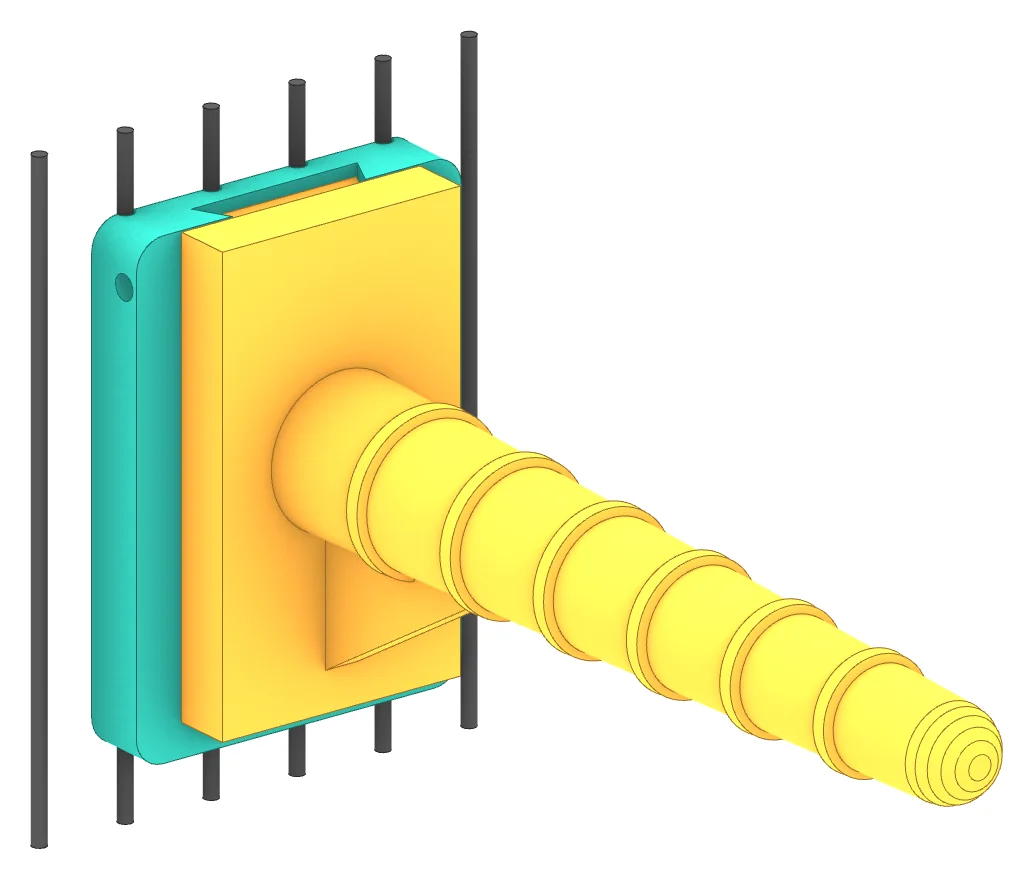
PP-1 Grip Perch
179 mm reach1 mount
A fully printed, tapered perch that plugs into a PH-1 head.
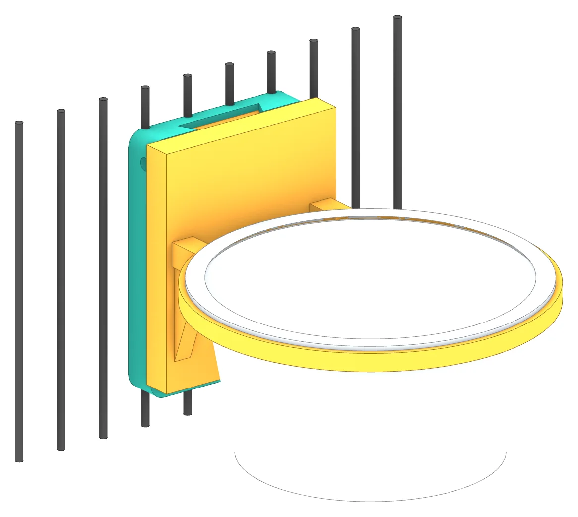
BH-1 Bowl Holder
139 mm reach1 mount
Holds a standard 4″ stainless coop cup that lifts straight out.
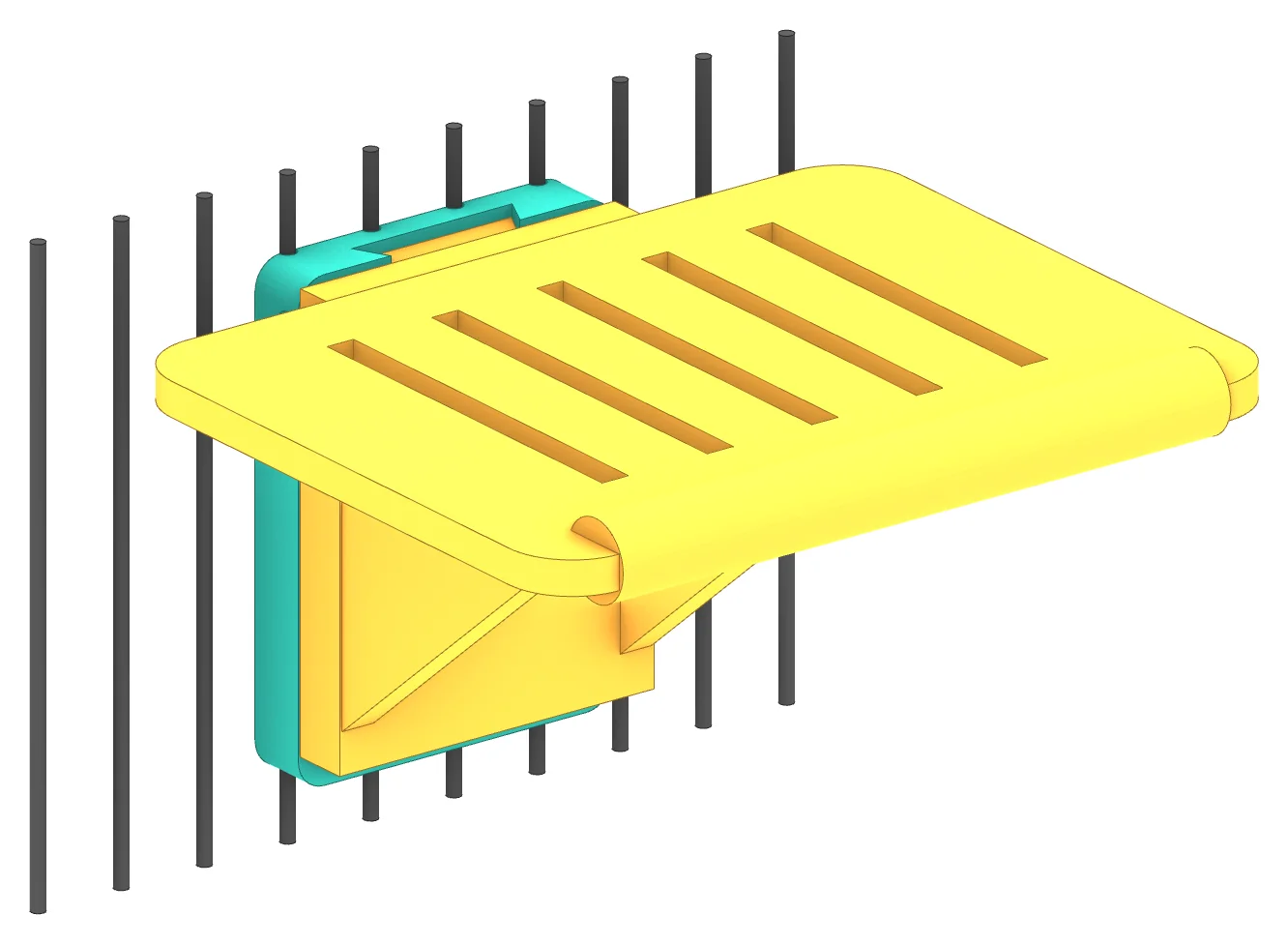
LP-1 Landing Pad
131 mm reach1 mount
A slotted 140 × 110 mm deck for landing and resting.
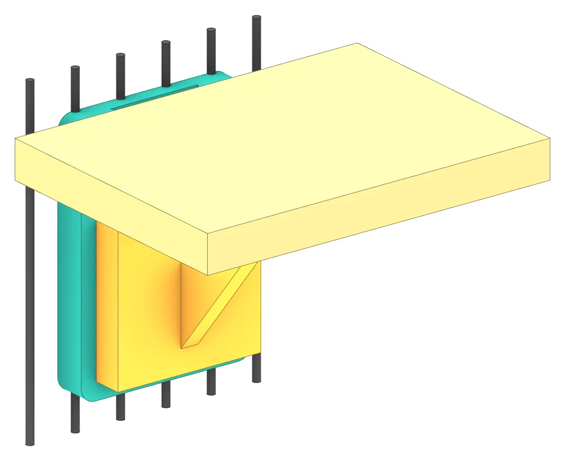
SB-1 Shelf Bracket
110 mm reach1 mount
An L-bracket head for 1/2″ wood shelves, single or in pairs.
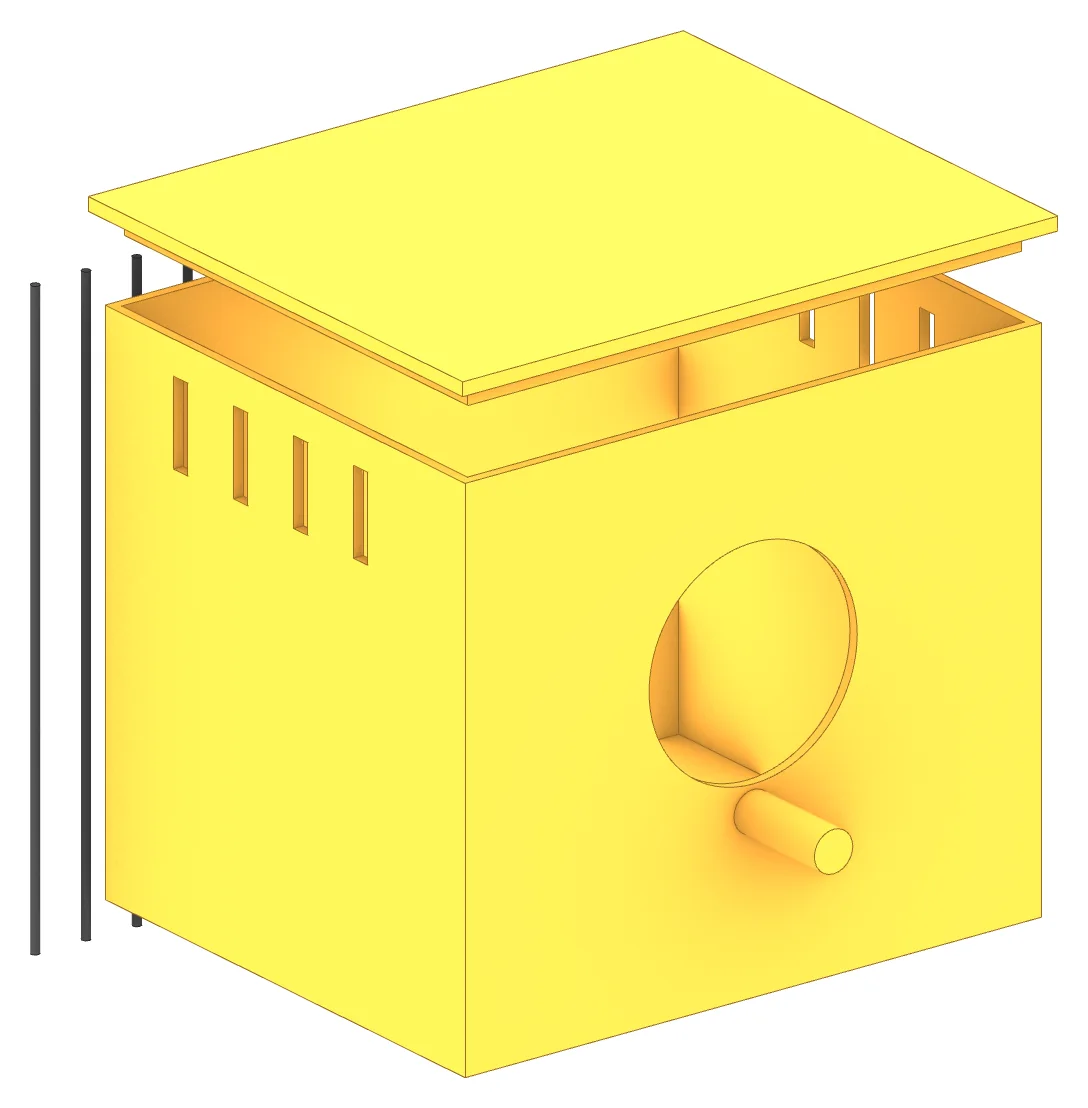
NB-1 Hideout Box
195 mm reach2 mounts
An enclosed hideout that hangs from two mounts.
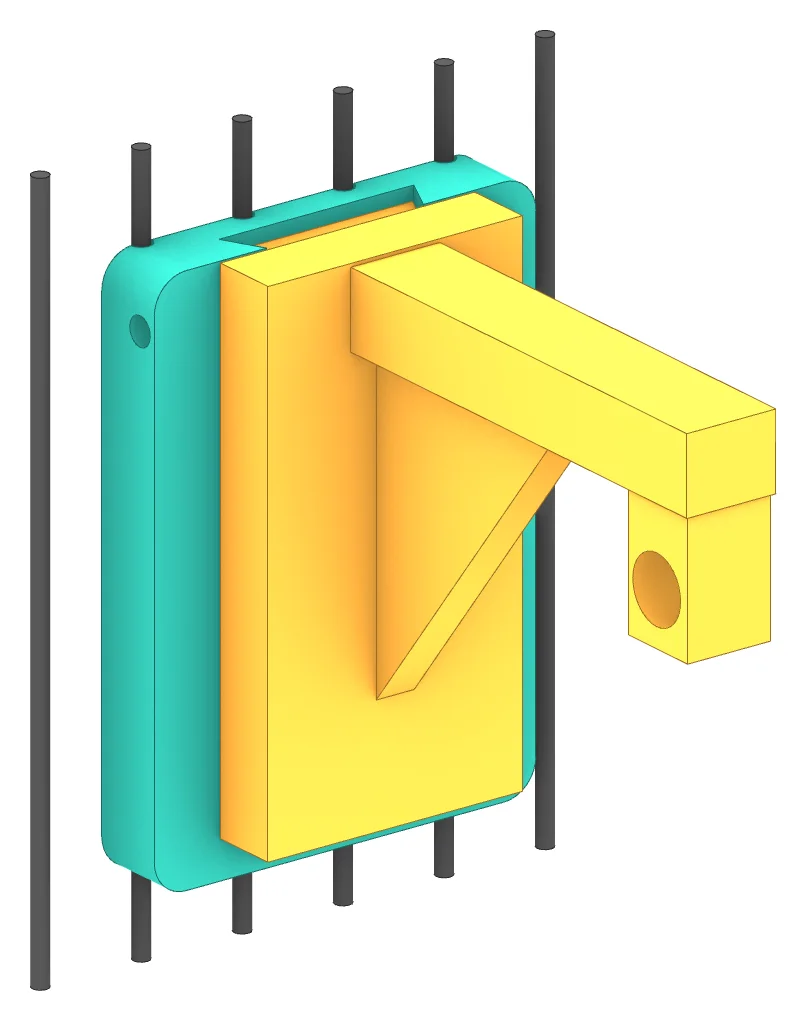
TH-1 Toy Hanger
92 mm reach1 mount
Hangs toys clear of the wall on a stainless quick link.
Nine accessory types, all on the same mount. Open one for its design, options, parts and dimensions.
MP-1 Wire Mount Kit ShowHide
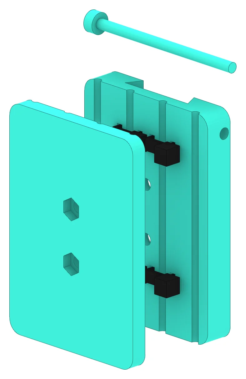
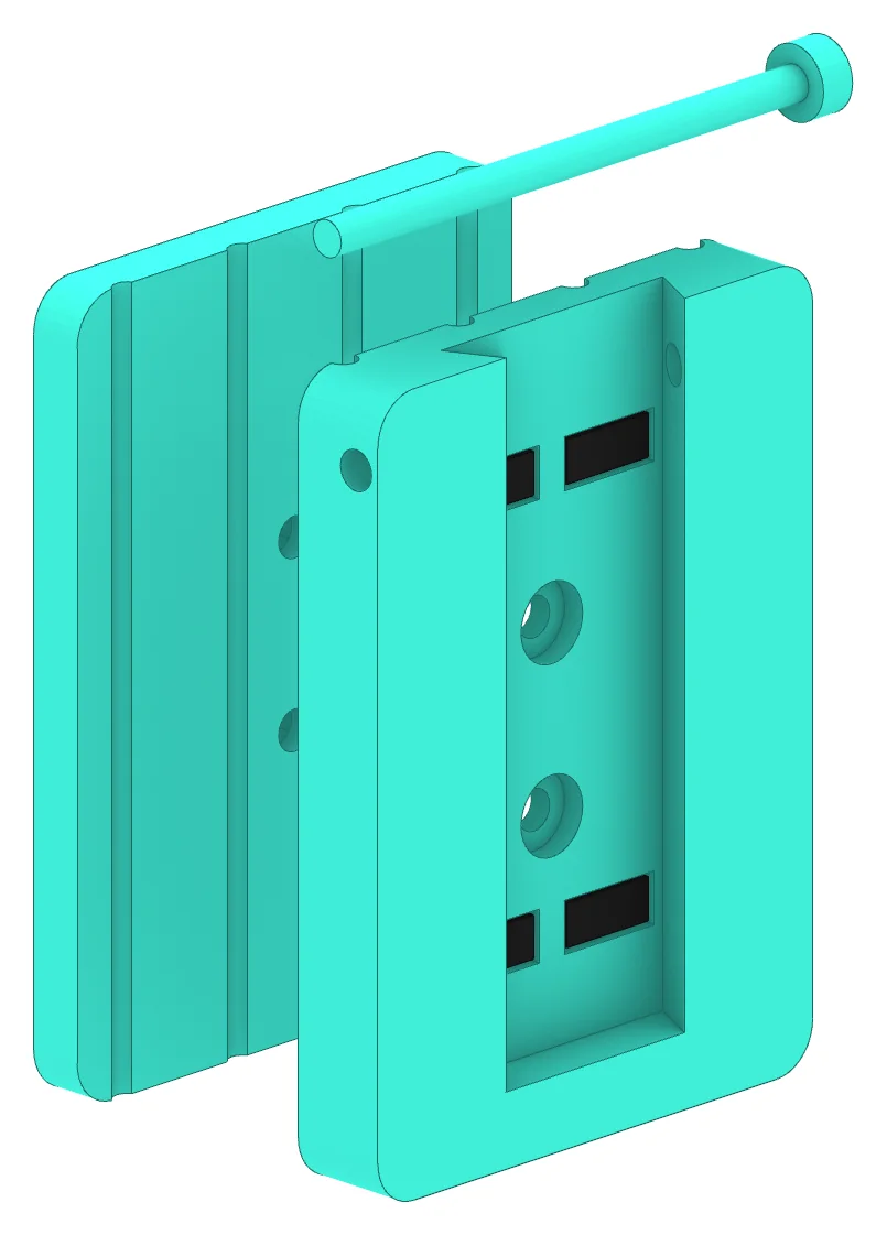
MP-1 is a 60 × 84 × 11 mm printed plate. Its back carries four half-round grooves on the cage’s 5/8″ (15.875 mm) wire pitch, so it seats over four vertical wires and can’t slide sideways. The front has a dovetail channel that is open at the top and closed by a 6 mm stop at the bottom. A KA-1 key drops in from above and rests on the stop. The LK-1 pin then passes through a cross-bore 8 mm below the top edge, through both channel walls and the key tongue, so a bird can’t lift the accessory out.
Split for printing. The callouts match the parts below.
Features
- 4 × Ø3.2 mm wire grooves at 15.875 mm (5/8″) pitch
- Zip-tie slots above and below the centre line, sized for 4.8 mm ties
- 2 × M4 clearance holes (Ø4.4 mm, Ø8.5 mm counterbore) 20 mm apart in the channel floor
- Ø4.3 mm LK-1 cross-bore, 8 mm below the top edge
- Dovetail channel: 25 mm mouth, 30.4 mm base, 6 mm deep
Options
- Zip-tie fixing
- 4 × 4.8 mm ties through the slots and around the wires. Quickest; nothing is needed outside the cage.
- Bolted fixing
- BP-1 backer outside the cage, 2 × M4 screws from the channel side into M4 nuts held in BP-1’s hex pockets. Both plates have matching wire grooves, so the wires are clamped between them. Use it for heavy accessories or positions a bird works at.
Parts
| Callout | Part | Qty | Source |
|---|---|---|---|
| 1 | MP-1 wire mount | 1 | P1 |
| 2 | LK-1 lock pin | 1 | P1 |
| 3 | BP-1 backer (bolted option) | 0–1 | P6 |
| 4 | Zip tie, 4.8 mm | 4 | Buy |
| 5 | or M4 screw + M4 hex nut | 2 + 2 | Buy |
Dimensions
- MP-1 plate
- 60 × 84 × 11 mm
- BP-1 backer
- 60 × 84 × 6 mm
- LK-1 pin
- Ø8 head, Ø3.9 × 68.5 mm
- Wire pitch
- 15.875 mm (5/8″)
In the Sample Cage
11 mounts in the sample layout, all zip-tied; 12 are printed (one spare).
PH-1 Dowel Perch ShowHide
The PH-1 head is a 50 × 78 mm plate with a Ø32 mm boss around a Ø19.4 mm socket, sized for a standard 3/4″ (19.05 mm) dowel. The dowel sticks straight out from the wall. A Ø3.5 mm radial hole through the boss takes a small screw to stop the dowel turning or pulling out.
Split for printing. The callouts match the parts below.
Features
- Ø19.4 mm socket for 3/4″ dowel
- Ø3.5 mm radial retaining hole
- 4 × M3 counterbored holes (Ø3.4 / Ø6.4 mm) on the 34 × 58 mm key pattern
Options
- Dowel length
- Cut to suit. The catalog sample uses 150 mm; the sample cage uses 8″ (203 mm).
- Printed perch
- The same head takes the PP-1 grip perch instead of a dowel.
Parts
| Callout | Part | Qty | Source |
|---|---|---|---|
| 1 | MP-1 mount kit | 1 | P1 |
| 2 | KA-1 key adapter | 1 | P2 |
| 3 | PH-1 perch head | 1 | P3 |
| 4 | 3/4″ hardwood dowel | 1 | Cut |
| 5 | M3 screw / M3 heat-set insert | 4 / 4 | Buy |
Dimensions
- Head plate
- 50 × 78 mm
- Head depth
- 39.5 mm
- Socket
- Ø19.4 mm in Ø32 mm boss
In the Sample Cage
Wall J (left side), lower zone, 8″ dowel.
PH-2 Corner Perch ShowHide
PH-2 is PH-1 with the socket turned 45° in plan, made as a mirrored pair, PH-2L and PH-2R. Alone, it holds a dowel at 45° to the wall. As a pair on the two walls that meet at a corner, both sockets point along one dowel, which bridges the corner. In the sample cage a 9.3″ dowel spans walls A and B.
Split for printing. The callouts match the parts below.
Features
- Socket axis 45° to the wall, horizontal
- Mirrored L and R heads
- Same Ø19.4 mm socket and Ø3.5 mm retaining hole as PH-1
Options
- Single (L or R)
- Angled cantilever perch from one mount.
- Pair (L + R)
- Corner bridge: one dowel between mounts on adjacent walls, cut to span.
Parts
| Callout | Part | Qty | Source |
|---|---|---|---|
| 1 | MP-1 mount kit | 1–2 | P1 |
| 2 | KA-1 key adapter | 1–2 | P2 |
| 3 | PH-2L and/or PH-2R head | 1–2 | P3 |
| 4 | 3/4″ hardwood dowel | 1 | Cut |
| 5 | M3 screw / insert (per head) | 4 / 4 | Buy |
Dimensions
- Head plate
- 50 × 78 mm
- Head depth
- 51.1 mm
- Width over socket
- 64.6 mm
In the Sample Cage
L + R pair on walls A and B, lower zone, 9.3″ dowel across the corner.
PP-1 Grip Perch ShowHide
PP-1 takes the place of a dowel in a PH-1 head. It is 190 mm long and tapers from 26 mm at the root to 16 mm at the tip, with raised grip rings along its length, so a bird can pick the diameter it grips. A Ø19 mm spigot at the root fits the 3/4″ socket.
Split for printing. The callouts match the parts below.
Features
- 190 mm long, 26 → 16 mm taper
- Grip rings along the length
- Ø19 mm spigot fits the PH-1 socket
- Prints lying down on P3, no wood needed
Options
- Swap
- Interchangeable with a 3/4″ dowel in any PH-1 head.
Parts
| Callout | Part | Qty | Source |
|---|---|---|---|
| 1 | MP-1 mount kit | 1 | P1 |
| 2 | KA-1 key adapter | 1 | P2 |
| 3 | PH-1 perch head | 1 | P3 |
| 4 | PP-1 grip perch | 1 | P3 |
| 5 | M3 screw / insert | 4 / 4 | Buy |
Dimensions
- Length
- 190 mm
- Diameter
- 26 → 16 mm taper
- Spigot
- Ø19 mm
In the Sample Cage
Wall K (right side), upper zone.
BH-1 Bowl Holder ShowHide
A low-profile bracket carries a 6 mm ring, Ø120 mm outside and Ø104 mm inside, fixed with 2 × M3 screws. The cup drops through the ring and hangs by its Ø112 mm rim, so it lifts straight out for cleaning without disturbing the mount.
Split for printing. The callouts match the parts below.
Features
- Ring Ø120 / Ø104 × 6 mm
- 2 × M3 counterbored holes in the ring, Ø2.6 mm pilots in the bracket
- Bracket only 19.5 mm deep
Options
- Cup
- Any 4″ coop cup with a rim larger than Ø104 mm.
Parts
| Callout | Part | Qty | Source |
|---|---|---|---|
| 1 | MP-1 mount kit | 1 | P1 |
| 2 | KA-1 key adapter | 1 | P2 |
| 3 | BH-1 bracket | 1 | P4 |
| 4 | BH-1 ring | 1 | P4 |
| 5 | 4″ stainless coop cup | 1 | Buy |
| 6 | M3 screw / insert (head) | 4 / 4 | Buy |
| 7 | M3 screw (ring) | 2 | Buy |
Dimensions
- Ring
- Ø120 / Ø104 × 6 mm
- Bracket
- 64 × 78 × 19.5 mm
- Cup
- Ø112 mm rim, 56.5 mm deep
In the Sample Cage
Wall A, lower zone.
LP-1 Landing Pad ShowHide
A 140 × 110 × 12 mm deck with R12 corners sits on a bracket with twin gussets. Five through-slots let droppings and water through and give the feet some grip, and a raised rail runs along one edge. The deck is fixed to the bracket with 2 × M3 screws through counterbored holes.
Split for printing. The callouts match the parts below.
Features
- Deck 140 × 110 × 12 mm, R12 corners
- 5 through-slots
- Raised rail along one edge
- 2 × M3 counterbored deck screws into Ø2.6 mm pilots
Options
- Deck
- Prints separately from the bracket, so a worn deck can be replaced on its own.
Parts
| Callout | Part | Qty | Source |
|---|---|---|---|
| 1 | MP-1 mount kit | 1 | P1 |
| 2 | KA-1 key adapter | 1 | P2 |
| 3 | LP-1 bracket | 1 | P5 |
| 4 | LP-1 deck | 1 | P5 |
| 5 | M3 screw / insert (head) | 4 / 4 | Buy |
| 6 | M3 screw (deck) | 2 | Buy |
Dimensions
- Deck
- 140 × 110 × 12 mm
- Bracket
- 60 × 78 × 80.5 mm
In the Sample Cage
Wall J (left side), upper zone.
SB-1 Shelf Bracket ShowHide
SB-1 is a gusseted L-bracket head. Its top flange has 2 × Ø4.2 mm holes for screws up into a 1/2″ (12.7 mm) wood board. One bracket carries a small rectangular shelf. Two brackets on the walls either side of a corner carry a triangular corner shelf.
Split for printing. The callouts match the parts below.
Features
- Top flange with 2 × Ø4.2 mm screw holes
- Diagonal gusset
- Takes 1/2″ (12.7 mm) board
Options
- Single
- One bracket under a rectangular board (catalog sample: 120 × 90 mm).
- Corner pair
- Two brackets on adjacent walls under a right-triangle board (sample: 221 mm legs, tips clipped).
- Long shelf
- Add brackets along one wall for a longer board.
Parts
| Callout | Part | Qty | Source |
|---|---|---|---|
| 1 | MP-1 mount kit | 1 | P1 |
| 2 | KA-1 key adapter | 1 | P2 |
| 3 | SB-1 shelf head | 1 | P6 |
| 4 | 1/2″ wood board | 1 | Cut |
| 5 | M3 screw / insert | 4 / 4 | Buy |
| 6 | Wood screw (Ø4.2 mm holes) | 2 | Buy |
Dimensions
- Head plate
- 50 × 78 mm
- Head depth
- 60.5 mm
- Board
- 1/2″ (12.7 mm)
In the Sample Cage
Corner pair on walls A and B, upper zone, triangular corner shelf.
NB-1 Hideout Box ShowHide
An enclosed box, 180 mm wide, 150 mm deep and 160 mm high, with a lift-off lid. The back wall carries two KA-1 screw patterns 95.25 mm apart, exactly six wire pitches, so the box hangs from two mounts and can’t rotate. The front has a Ø65 mm entry with a 12 mm dowel perch below it. Vent slots in the side walls and 6 × Ø5 mm floor holes let air and moisture out.
Split for printing. The callouts match the parts below.
Features
- Ø65 mm entry, Ø12.6 mm hole for a 12 mm dowel perch
- 2 key patterns at 95.25 mm (6 × 5/8″)
- Side vent slots, 6 × Ø5 mm floor holes
- Lid prints separately (P8), body open top up (P7)
Options
- Mounting
- Needs two mounts six wires apart at the same height.
Parts
| Callout | Part | Qty | Source |
|---|---|---|---|
| 1 | MP-1 mount kit | 2 | P1 |
| 2 | KA-1 key adapter | 2 | P2 |
| 3 | NB-1 body | 1 | P7 |
| 4 | NB-1 lid | 1 | P8 |
| 5 | 12 mm dowel, 45 mm | 1 | Cut |
| 6 | M3 screw / insert | 8 / 8 | Buy |
Dimensions
- Body
- 180 W × 150 D × 160 H mm
- Lid
- 186 × 156 × 10 mm
- Entry
- Ø65 mm
In the Sample Cage
Wall A, upper zone, on two mounts.
TH-1 Toy Hanger ShowHide
A head with a gusseted arm that reaches about 75 mm out from the key and ends in a block with a vertical Ø10 mm hole. A stainless quick link through the hole carries a toy, so toys hang clear of the wall and can be swapped without tools.
Split for printing. The callouts match the parts below.
Features
- Ø10 mm hole for a quick link
- Gusseted arm, ≈75 mm reach
Options
- Toys
- Anything that hangs from a quick link.
Parts
| Callout | Part | Qty | Source |
|---|---|---|---|
| 1 | MP-1 mount kit | 1 | P1 |
| 2 | KA-1 key adapter | 1 | P2 |
| 3 | TH-1 toy hanger head | 1 | P6 |
| 4 | Stainless quick link | 1 | Buy |
| 5 | M3 screw / insert | 4 / 4 | Buy |
Dimensions
- Head plate
- 50 × 78 mm
- Reach
- 75.5 mm
- Link hole
- Ø10 mm
In the Sample Cage
Wall B, upper zone.
Options
Every head bolts to the same KA-1 key and every key fits every MP-1 mount. Options change what an accessory carries or how many mounts it uses.
| Accessory | Head | Buy or cut | Variants | Reach (mm) |
|---|---|---|---|---|
| PH-1 Dowel perch | PH-1 | 3/4″ dowel | Dowel length, Printed perch | 174 |
| PH-2 Corner perch | PH-2L / PH-2R | 3/4″ dowel | Single (L or R), Pair (L + R) | 142 |
| PP-1 Grip perch | PH-1 | — | Swap | 179 |
| BH-1 Bowl holder | BH-1 bracket | 4″ stainless cup | Cup | 139 |
| LP-1 Landing pad | LP-1 bracket | — | Deck | 131 |
| SB-1 Shelf bracket | SB-1 | 1/2″ board, wood screws | Single, Corner pair, Long shelf | 110 |
| NB-1 Hideout box | Built into body | 12 mm dowel | Mounting | 195 |
| TH-1 Toy hanger | TH-1 | Stainless quick link | Toys | 92 |
Compatibility
- Mount fixing
- Zip ties (4 per mount) or bolted with a BP-1 backer and 2 × M4. The choice is per mount and doesn’t affect what can be attached.
- Interchangeable parts
- A PH-1 head takes a 3/4″ dowel of any length or the PP-1 grip perch. A PH-2 pair takes one dowel across a corner. SB-1 takes any 1/2″ board.
- Placement
- Horizontal position steps in whole 5/8″ wire pitches. Height is free along the vertical wires, between cross-bars. Two-mount accessories need both mounts level.
Sample Layout
The Sample Cage
Eleven mounts carry eight accessories. Resting and shelter sit in the upper zone; perches, food and water stay low. The doors in J, K and E stay clear.
| Accessory | Zone | Wall | Mounts | Height (in) |
|---|---|---|---|---|
| TH-1 Toy hanger | Upper | B | 1 | 50.9 |
| LP-1 Landing pad | Upper | J | 1 | 48.9 |
| PP-1 Grip perch | Upper | K | 1 | 42.9 |
| SB-1 Shelf bracket | Upper | B + A | 2 | 40.9 |
| NB-1 Hideout box | Upper | A | 2 | 34.5 |
| PH-1 Dowel perch | Lower | J | 1 | 20.9 |
| PH-2 Corner perch | Lower | B + A | 2 | 16.9 |
| BH-1 Bowl holder | Lower | A | 1 | 12.9 |
Walls A and B are the back panels L-1 and L-2; J and K are the side panels. Height is to the mount centre, above the floor grate.
Plan
Mount positions. Filled: upper zone. Open: lower zone.
Interior Elevations
The four walls that carry accessories, unfolded and seen from inside, at one scale: K, the right side; A and B, the back panels L-1 and L-2; and J, the left side. Outlined: the mounts.
Printing

The Eight Plates
Eight plates on a 220 × 220 mm bed, parts in print orientation, no supports.
- Material
- PETG
- Walls
- 4
- Infill
- 40% gyroid
- Bed
- 220 × 220 mm
- Supports
- None: parts are laid out in print orientation
- Sample layout
- Run P1 and P2 twice (12 mounts and keys)
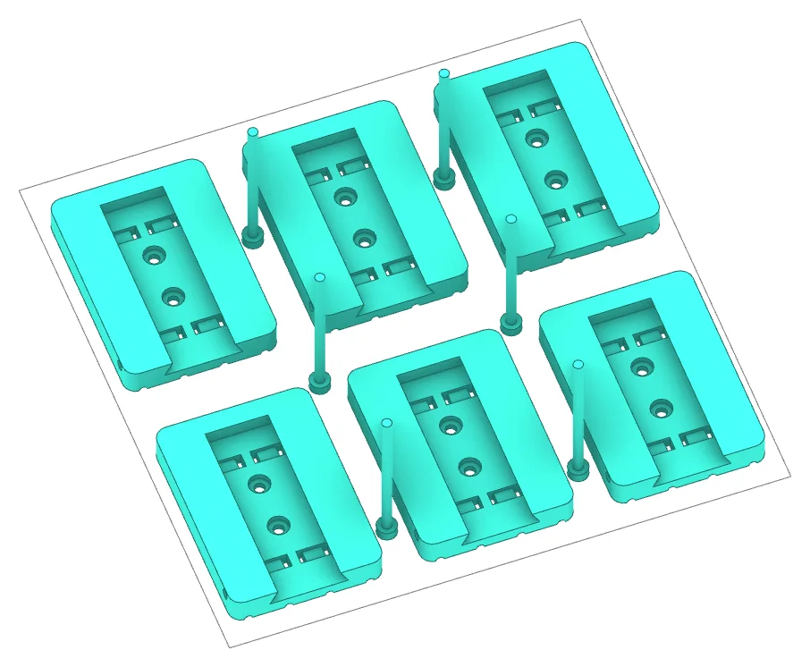
P1 Mount
MP-1 × 6, LK-1 × 6
244 cm³. Print twice for the sample layout.
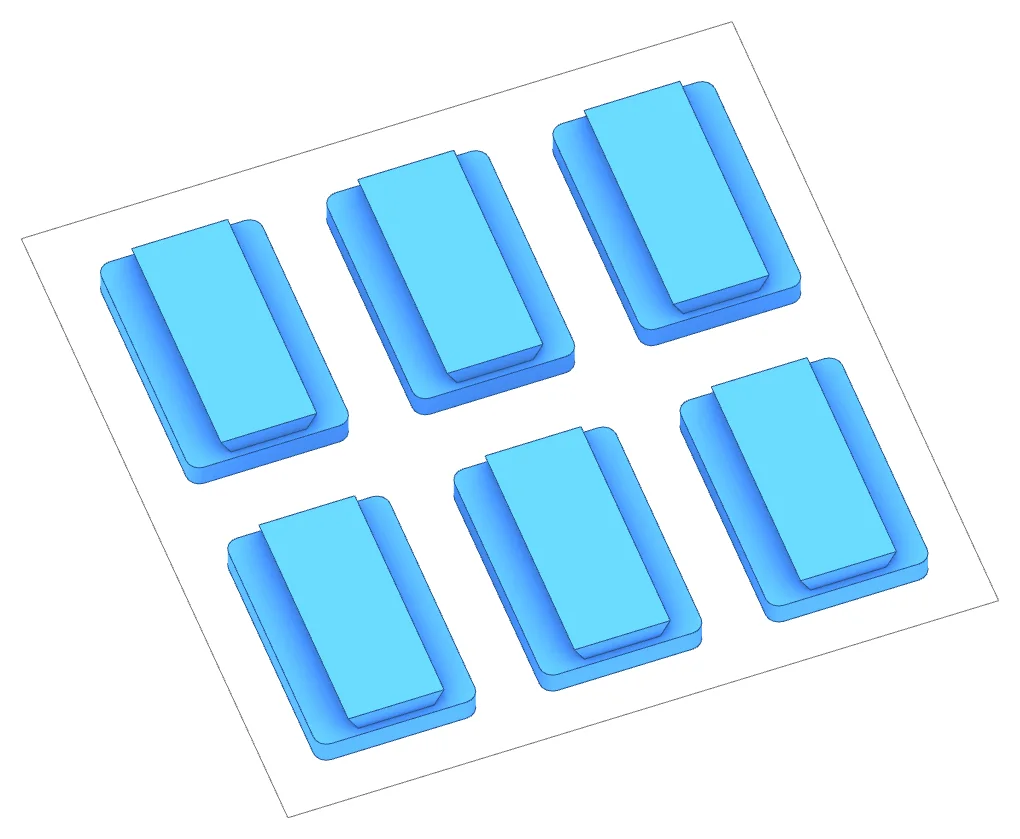
P2 Key Adapter
KA-1 × 6
256 cm³. Print twice for the sample layout. Tongue up.
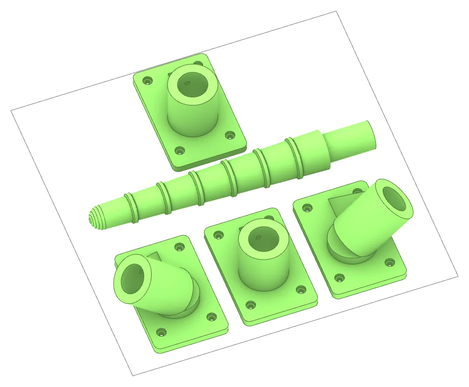
P3 Perch
PH-1 × 2, PH-2L × 1, PH-2R × 1, PP-1 × 1
226 cm³. PP-1 lies on its flat side.
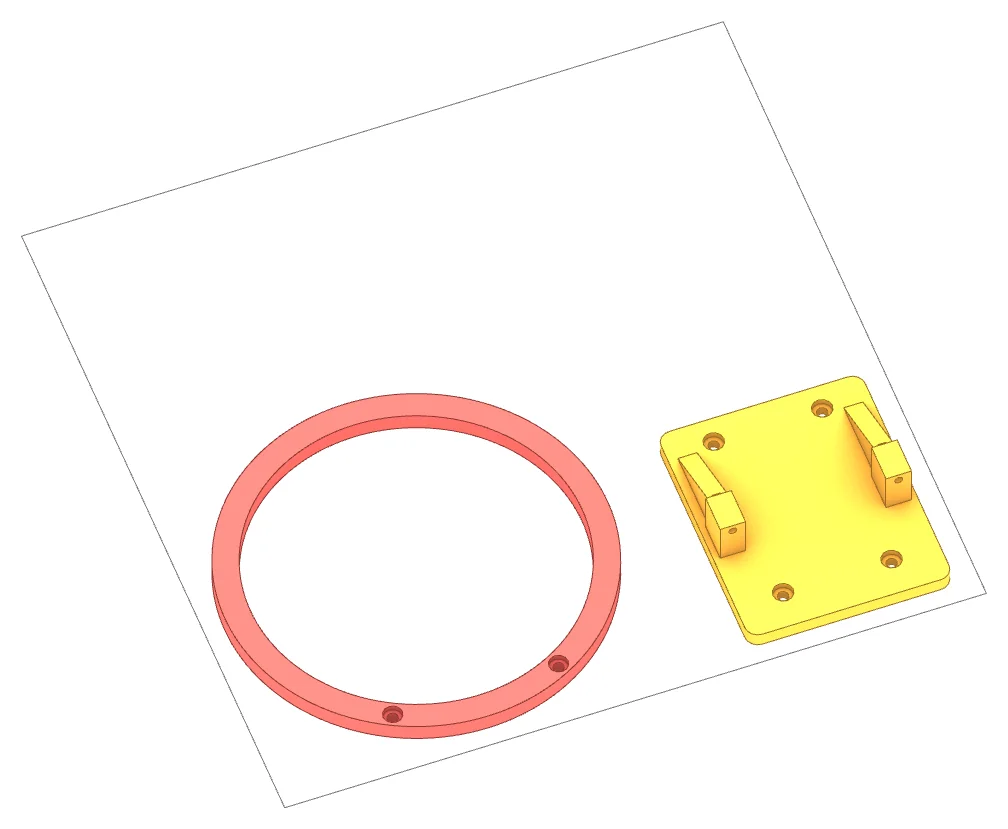
P4 Feeding
BH-1 ring × 1, BH-1 bracket × 1
46 cm³.
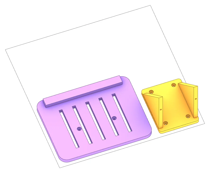
P5 Platform
LP-1 deck × 1, LP-1 bracket × 1
141 cm³.
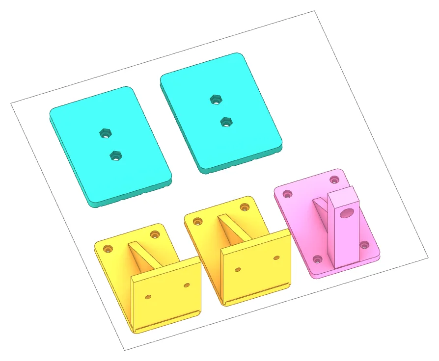
P6 Structure and Toy
SB-1 × 2, TH-1 × 1, BP-1 × 2
184 cm³. BP-1 backers for bolted mounts.
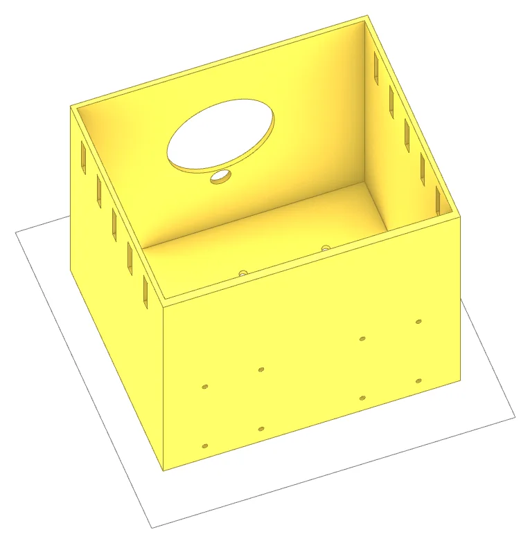
P7 Shelter
NB-1 body × 1
425 cm³. Open top up.
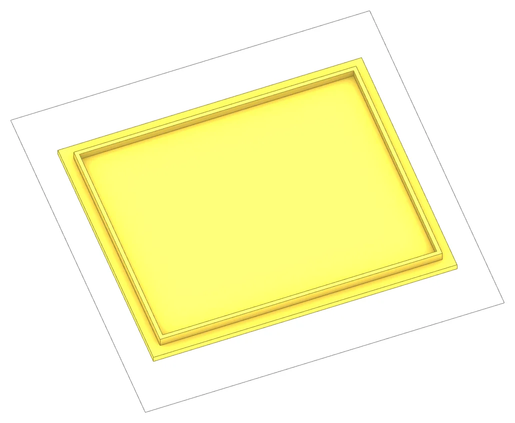
P8 Shelter
NB-1 lid × 1
148 cm³. Top down.
cm³ is the solid model volume, an upper bound on material.
Materials
What to print and buy for the sample layout: eight accessories on eleven mounts, all zip-tied.
Printed
| Part | Qty | Plate | Note |
|---|---|---|---|
| MP-1 wire mount | 12 | P1 ×2 | 11 used + 1 spare |
| LK-1 lock pin | 12 | P1 ×2 | 11 used + 1 spare |
| KA-1 key adapter | 12 | P2 ×2 | 11 used + 1 spare |
| BP-1 backer | 2 | P6 | Only for bolted mounts |
| PH-1 perch head | 2 | P3 | PH-1 dowel perch + PP-1 grip perch |
| PH-2L / PH-2R corner perch head | 1 + 1 | P3 | Corner pair |
| PP-1 grip perch | 1 | P3 | |
| BH-1 bracket + ring | 1 + 1 | P4 | |
| LP-1 bracket + deck | 1 + 1 | P5 | |
| SB-1 shelf head | 2 | P6 | Corner shelf pair |
| TH-1 toy hanger head | 1 | P6 | |
| NB-1 body + lid | 1 + 1 | P7, P8 |
Hardware
| Item | Qty | Note |
|---|---|---|
| Zip tie, 4.8 mm wide | 44 | 4 per mount (zip-tie fixing) |
| M3 heat-set insert (Ø4.0 mm hole) | 44 | 4 per KA-1 |
| M3 screw, head to key | 44 | 4 per head; 8 for NB-1 |
| M3 screw, BH-1 ring + LP-1 deck | 4 | 2 each |
| Wood screw for SB-1 (Ø4.2 mm holes) | 4 | 2 per bracket |
| Small screw for perch retaining hole (Ø3.5 mm) | 0–4 | Optional; PH-1 ×2, PH-2 ×2 |
| M4 screw + M4 hex nut | 0 | 2 + 2 per bolted mount, if used |
| Stainless coop cup, 4″ | 1 | BH-1 |
| Stainless quick link | 1 | TH-1 |
Wood, to Buy or Cut
| Item | Size | Use |
|---|---|---|
| 3/4″ hardwood dowel | 8″ + 9.3″ | PH-1 perch; PH-2 corner span |
| 12 mm dowel | 45 mm | NB-1 entry perch |
| 1/2″ wood board | Right triangle, 221 mm legs, tips clipped | SB-1 corner shelf |
Assembly
- P1 and P2 twice, P3–P8 once. PETG, 4 walls, 40% gyroid, no supports.
- Set inserts
- 4 × M3 heat-set inserts into the Ø4.0 mm holes on each KA-1.
- Fit heads
- Each head to a KA-1 with 4 × M3. NB-1 takes two keys and 8 screws.
- Add function parts
- Dowels, PP-1, cup ring, deck, shelf board, NB-1 dowel, quick link.
- Fix mounts
- MP-1 over four vertical wires, channel up; 4 zip ties, or M4 through to a BP-1 backer.
- Hang
- Lower each key into its mount until it rests on the bottom stop.
- Lock
- Push LK-1 through the side bore. To swap, pull the pin and lift the accessory out.
Care
- Check zip ties and LK-1 pins when cleaning; replace any tie a bird has chewed.
- Cup, deck and lid lift off for cleaning without removing the mount.
- Use untreated hardwood and stainless hardware where birds can reach.
Open Items
- Screw lengths (M3 head screws, M4 mount screws) and heat-set insert length aren’t set in the model. Insert holes in KA-1 are Ø4.0 mm.
- Wood screws for SB-1 (Ø4.2 mm holes) and the perch retaining screws (Ø3.5 mm holes) still need a size.
- The KA-1 tongue is ≈0.2 mm taller than the MP-1 channel is deep, so a seated key stands ≈0.2 mm proud of the mount face. Confirm this preload is intended.
- Check each mount position against the panel’s horizontal cross-bars before fixing.